![]()
HowTo connect our CNC MPG Terminal to Mach 3
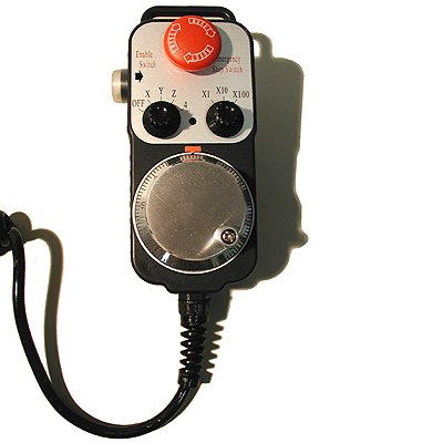 |
Our Electronic Pendant has the following Controls
Click Here for the wiring plan of this MPG Terminal In this document we will explain how to connect the pendant to your PC so that it will work with Mach3. The Pendant is connected to Mach3 with a second printerport. So first you will need to buy a second printerport card for your PC and a printerport breakout card so that you can connect the wires of the pendant to the second printerport card in your PC. Make sure your second (LPT2) parallel port (or third) is set to ECP mode in your computer BIOS. To use our Pendant pins 2 to 9 need to be used as inputs. This is only possible if the the Port is operating in ECP mode. You need to reboot your computer and go to your BIOS setup to change this setting at computer startup Connecting the Pendant is at your own risk, we do not except any liability for any situation resulting from errors we might have made in this document or missing information we might have forgotten to put in this document. |
|
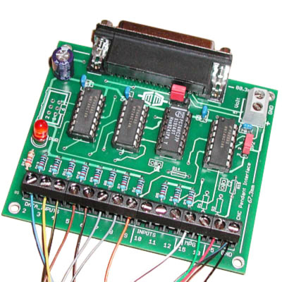
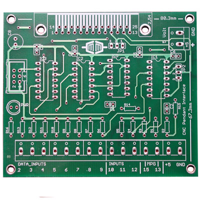
The MPG interface baord provides a safe way to connect our (or other) CNC Pendant to your computer. It also supresses noise signals and gives an extra Function , when you press the side Button the movement is Fast if you release this Button the movement is step by step, you do not get this function if you do not use the MPG Interface Board Unsere MPG Interface verstärkt die Eingangssignalen von unsere Elektronische Handrad und sorgt für die benötigten pull up Widerstände. Mit das Interface kann man weiter weg von der PC arbeiten ohne das es Probleme gibt mit Störsignale. Auch Bietet das Interface ein extra Funktion nämlich Schnell Fahren oder schritt für schritt fahren. Diese Funktion wird mit die Knopf auf die linker Seite bedient. Ohne Platine hat man diese Funktion nicht You will need a 5 Volt power source for powering the Manual Pulse Generator Interface. Out MPG cnc interface let you connect up to 11 switches and 1 Manual Pulse Generator to your PC. It also add the possiblity to switch from velocity move to single step mode by pushing the side switch of our CNC MPG pendant. This interface can also be used for other MPG pendants and home made pendant devices. To enble the use mechanical MPG's there is a debounce circuit available on the board (R1,R2,R14,R15,C1,C2). Because we use an optical MPG with buffer we not need this optional debouncing circuits with our CNC MPG pendant. The unused outputs pin 1,14,16 7 17 of the printerport are buffered and wired to the 6 pin pinhearder just above the LED, so that they can be used for other boards. Klicken Sie hier fur eine Teileliste Click here to download the Build description for DIY build of this interface
Wire Connections Markus Mechatronics MPG Pendant to Markus Mechatronics MPG Interface
Notes 1. Any changes to the axis choice and step size choice are sent to the computer only when the side switch is pushed 2.Input pin nr. 10 of the printerport is activated if the side button is pressed, if pin 2&3 of JP1 are connected , if pin 1&2 is connected then pin 10 is a normal input, when pin 1&2 are connected input 10 can not be used for other purposes 3. If pin 1&2 of JP2 is connected then input pin nr. 12 will become the inverted value of input 10, if pin 2&3 are connected then pin 12 is a normal input, if pin 12 is being used as the inverted value of pin 10 then pin 12 cannot be used for other purposes. Click here to download the Build description for DIY build of this interface How to Configure Mach 3 for our our CNC MPG Terminal |
||||||||||||||||||||||||||||||||||||||||||||||||||
 |
||||||||||||||||||||||||||||||||||||||||||||||||||
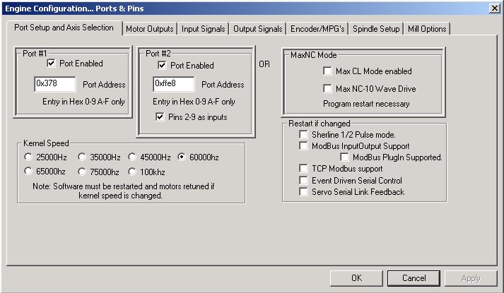
| After you have connected the our CNC MPG Pendant (terminal) to our Interface its time to tell Mach3 that you want to use the second Printer port in the program. This is done under menu item Ports and Pins check the box "Port Enabled" under Port #2. Fill in the cards Base address. You can find the second Printer ports Base Address under "Windows Device Manager". Also check the box "pins 2-9 as inputs" You can check to see if the card is working in the Diagnostic screen. The little green lights should change when you play around with the switches on the pendant. Note the address (0xffe8) shown in this screen shot may not be the same as the one your computer may use, this value does not have to match this example. | ||||||||||||||||||||||||||||||||||||||||||||||||||
|
|
||||||||||||||||||||||||||||||||||||||||||||||||||
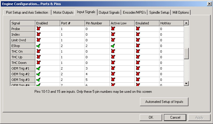
| Next task is to assign Triggers to the input lines of the second printer port. Under tab "Input Signals" set the signals as above if you wired up the pendant using the wiring table we have made. Check if the big red Emergency Stop is not pressed. Turn it to unlock it from a "pressed" state. If the Emergency Stop is pressed nothing will work and you cannot test the pendant. | ||||||||||||||||||||||||||||||||||||||||||||||||||
 |
||||||||||||||||||||||||||||||||||||||||||||||||||
|
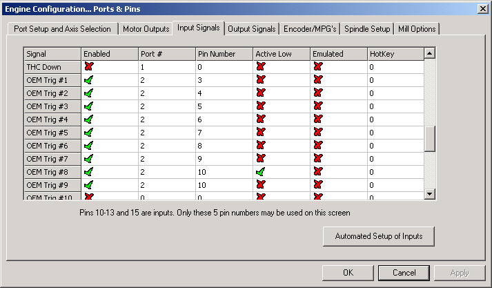
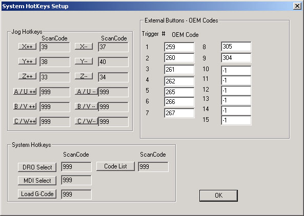
After the 7 OEM Triggers have been mapped to input lines on the second Printer Port its time to Tell Mach3 what to do when the switches are activated. This is done in the "System Hotkeys" menu. On this webpage you can find the OemCodes we need to manipulate the behaviour of the Jogging system.
Now its time to set up the Rotary Encoder |
||||||||||||||||||||||||||||||||||||||||||||||||||
 |
||||||||||||||||||||||||||||||||||||||||||||||||||
|
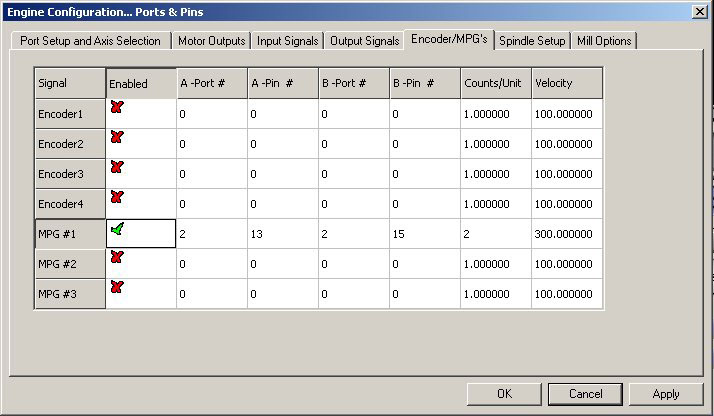
Under menu item "Ports and Pins" open Tab "Encoder/MPG's" set the MPG# 1 to the values as shown in the above image if you used our wiring example to connect the pendant to your second printer port. You can allready set the "Counts/Unit" if you want and fill in a Velocity. This can also be done later in the calibration screen of the MPG jogging screen "CAL". If you want the increase/decrease direction to be the other way round you can always swap wires 13 and 15. Once this last stage is done you can test your pendant. Switch Jogging on in the Program Run screen. Call up the jogging screen by pressing the TAB button on your PC keyboard. Then set JOG MODE to MPG and set to Velocity/Step. If you slowly turn the Rotary encoder the value of the selected Axis should change. To change the selected Axis and/or to change the step size push the Enable button on the left side of the pendant and with your other hand turn the choice switches to the desired position. Watch the jogging screen as you change things to check if the program is responding. If there is a problem go to the Diagnostics screen to see if the problem is in the wiring (hardware) or in the settings of Mach3. Hardware problems can be, no +5 volt connected to the MPG wheel or Windows does not reconise your second printer port card. You may also have not correctly set the Base address of the second printer port card..
|
||||||||||||||||||||||||||||||||||||||||||||||||||
|
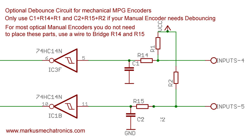
Debouncing circuits for other Manual Encoders For people who are not using our CNC Pendant or our MPG , but are using a Manual Encoder that needs debouncing here is the schematic of the optional debounce inputs. We do not use it with our Pendant or with our MPG's because it is not needed with these optical encoders. If you need to use the debouncing circuits you will have to calculate the values of R1, R14 and C1 (and R2,R15 and C2) yourself to suit your Encoder (pulses per rotation) and your wishes (max turn speed).
Note 1 : When testing with your Milling machine Off please realise that the update speed of the DRO's is done with the speed of that axis even if your mill is not on at the time you are testing. If you want fast response to the turning of the electronic handwheel during testing then you must change the max speeds and acceleration for the axises you are testing. Note 2:Input Pin 11 and 12 are unused when using our CNC MPG pendant, you can connect other switches to these inputs. If these switches are connected to the chasis of your machine then it is wise to use optocouplers or connect those inputs with our CNC printer port interface on printer Port 1. Remember that these switches must connect to GND when closed (pushed). Also outputs 1,14,16, and 17 are availible, if you have no need for these outputs do not solder the pinheader (as shown in the picture Note 3: This page can contain errors and we might have forgotten information needed to get your setup working. Please do not just copy the settings as shown here but try and understand the way the whole system works. If you have found a mistake or think we should add certain information please send us an email (contact page). |